Ct Circuit Diagram
Simplified equivalent circuit of ct Diagram wiring current transformer demand ct transformers hook controllers controller collection ups standard What is summation current transformer? definition & types
What is Current Transformer (CT)? Definition, Construction, Phasor
What is current transformer (ct)? definition, construction, phasor Circuit equivalent Current transformer sensor circuit
Ct cores primary circuit connection diagram
Circuit transformers cts talema burdenElectrical systems: ct and vt comparison and connection Circuit analysisEquivalent electric circuit of a ct..
Equivalent secondaryCt wiring diagram Ct vt connection pt sld line electrical load current voltage comparison systemCt secondary equivalent circuit diagram.

Solved create a block diagram of a ct circuit that would
Summation transformer current phase sequence zero phases comparing quantities relaying cts circuitglobeWiring diagram ct metering Ct scanner diagram block tomography gr next circuit above click size guru tech choose boardIntroduction to current transformers (cts) : the talema group.
Transformer current ct construction sensor ratio secondary working principle wire meter core power test work does circuit electrical ac voltageSensor circuit current ct transformer schematic practical varies output testing changes flow shows below much Equivalent simplifiedTransformer metering.

Measuring circuitlab
Energy sentryCt vt connection pt electrical measuring comparison burden Equivalent paktechpointHow to connect ct & pt to switchgear connection diagram.
Arduino sensor transformer burden wei hsiung huang calculationsCt secondary equivalent circuit diagram Ct wiring diagramCt cores secondary circuit connection diagram.

Ct diagram
Transformer current circuit ct diagram secondary types phasor construction primary definition circuitglobePublication equivalent Blog of wei-hsiung huang: working with current transformer (ct) sensorsEquivalent circuit of ct paktechpoint.
Equivalent circuit of ct (a) equivalent circuit of ct, (b) theElectrical systems: july 2012 Ct scan block diagramCircuit cores.

Transformer current
Cores secondaryBlock diagram of the ct scanner under repository-circuits -28115- : next.gr Transformer ct pt current potential grounding voltage high circuit electrical engineering(pdf) design and implementation of the ct analyzer on the basis of the.
Ground current fault connection transformers conection ct detection transformer phase connected wye difference circuit cts secondary grounded way systemCt circuit equivalent secondary diagram principle low basis analyzer implementation pressure test High voltage.


Ct Wiring Diagram
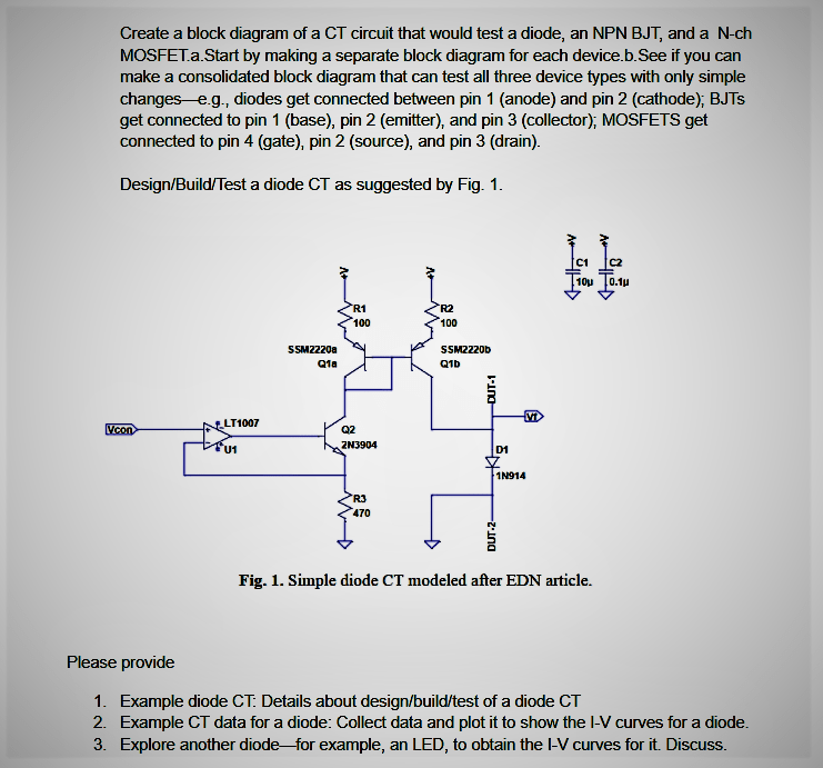
Solved Create a block diagram of a CT circuit that would | Chegg.com

CT cores primary circuit connection diagram | Download Scientific Diagram

EQUIVALENT CIRCUIT OF CT PAKTECHPOINT

Electrical Systems: July 2012

power - Current Transfomer (CT) ratio setting on energy meter

amplifier - CT measuring circuit with PIC - Electrical Engineering